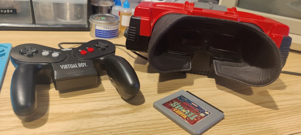
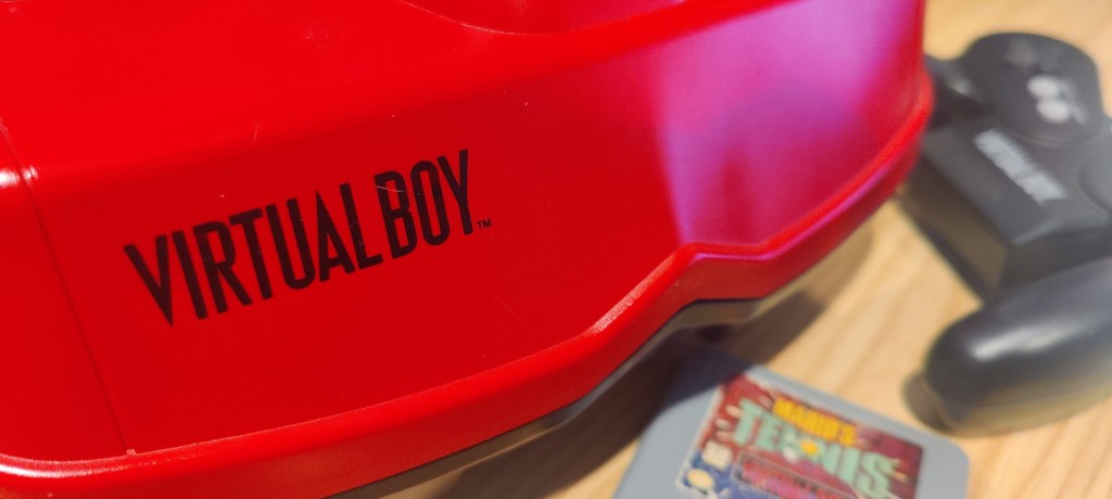
The Nintendo Virtual Boy doesn’t need an introduction. If you’re reading this, then you are already aware of the Red Brick, but I’ll throw you a nice bit of trivia: Did you know the WonderSwan and the Virtual Boy are directly related? Both projects were developed in collaboration with Gunpei Yokoi. Cool, huh?
Anyway, we aren’t here to talk about that. We are here because the Virtual Boy’s iconic red display isn’t looking all that hot.
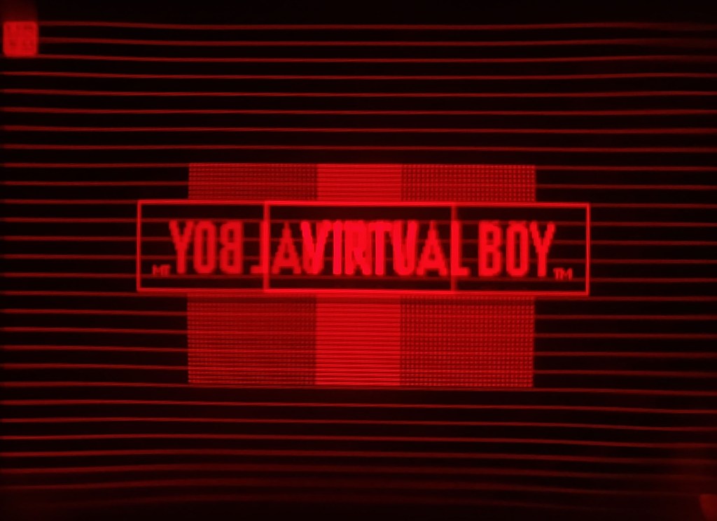
Spoiler alert: The Virtual Boy’s display has to be one of the most photogenic I’ve ever seen. I’ll go into some minor detail on how it actually works later.
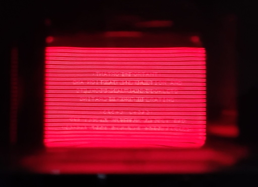
It’s pretty common nowadays to see a corrupted or missing image when trying to play the old Virtual Boy. It’s a tale as old as time, a song as old as rhyme: hot-bar-applied ribbon cables. If optical drives didn’t exist, this would be my arch nemesis.
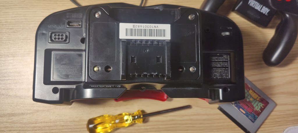
Once you crack open the ol’ VB, which is pretty easy if you have that Nintendo game-bit screwdriver, only 12 screws hide all its secrets.
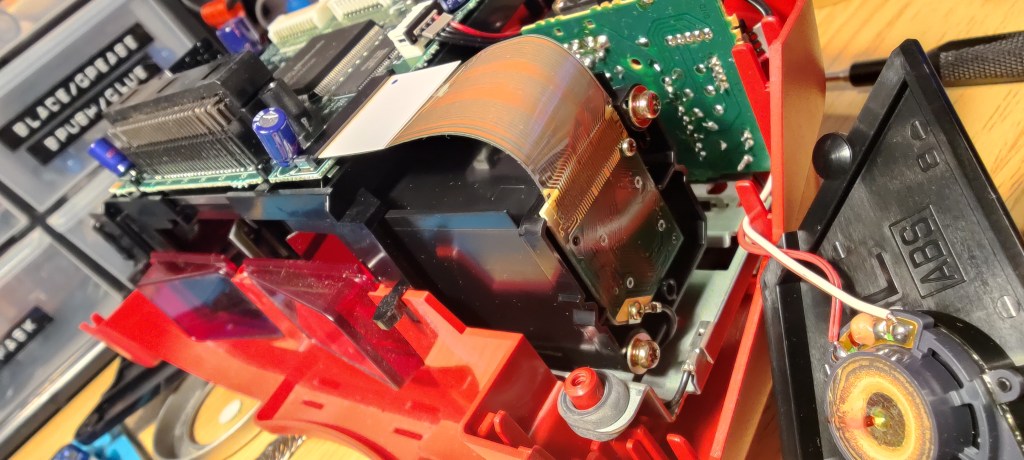
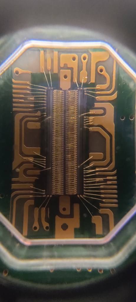
On both sides of the chassis are rectangular PCBs. They attach to the main board of the console via a ribbon cable. These little guys (both of them) are the display.
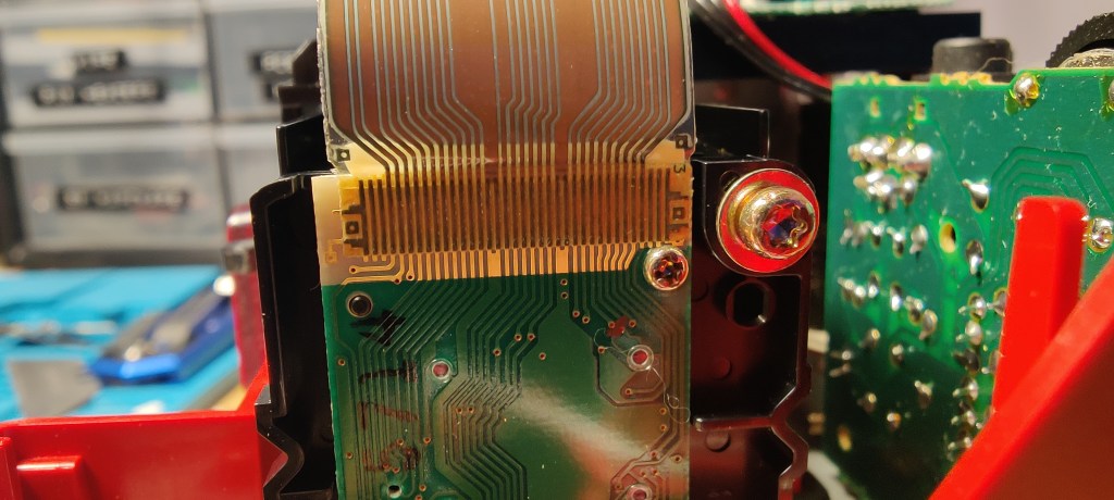
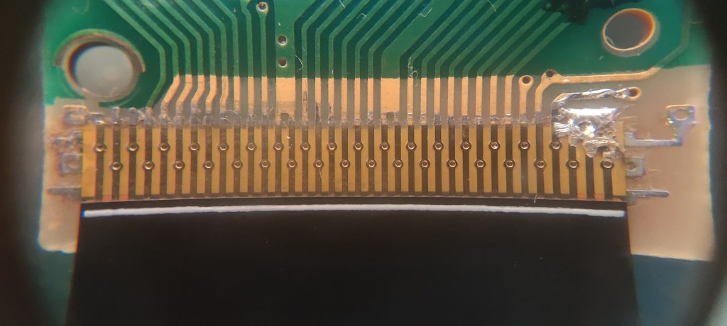
The main PCB has a nice push-fit ribbon cable connector. But on the display PCB, the ribbon cable is glued on. And that, right there, is the problem. Ugh, why glue!?
Over the years, the glue stops being good at gluing. It allows the ribbon cable to partly disconnect from the PCB, which gives you no display or lines on the image. No different from the aging Nintendo Game Boy.
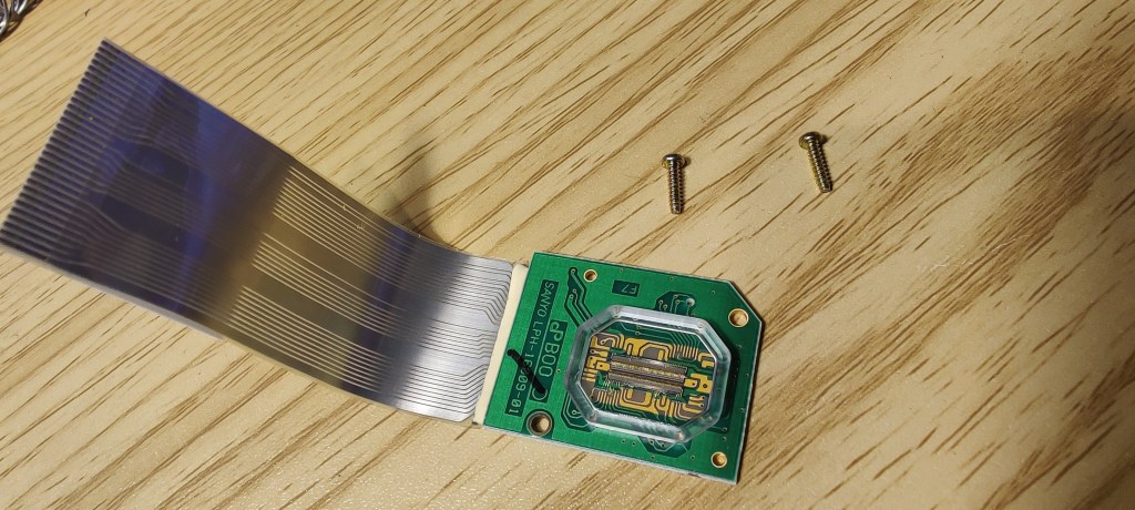
Just two screws hold the display PCB in place. And would you look at that, unlike modern headsets that have two displays, these aren’t LCDs. Once I fix the ribbon cable, I’ll show you how this thing actually works.
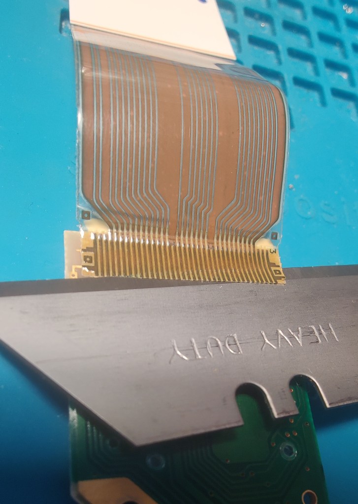
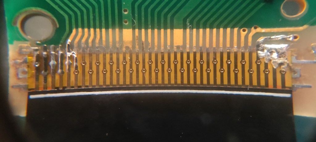
To remove the old cable, I just use a razor blade. I’ve done so many of these; I find this the best way.
Once the ribbon cable is removed, there will be a layer of adhesive on the copper traces. I run a hot soldering iron over it to remove the residual glue while also pre-tinning the traces.
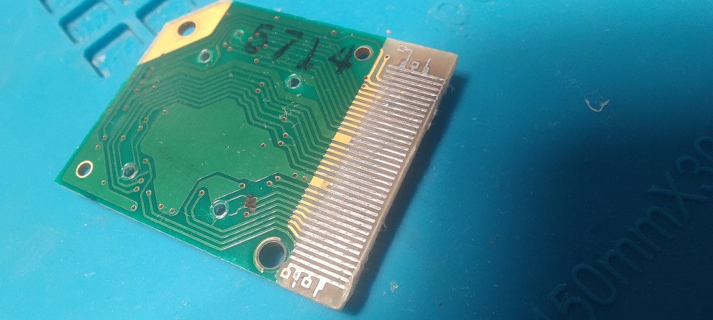
The replacement ribbon cables I use are from cardosicustom.
Once I have the new ribbon aligned, I’ll blob solder on one side. I’ll double-check the alignment, make adjustments if needed, and then solder the other side.
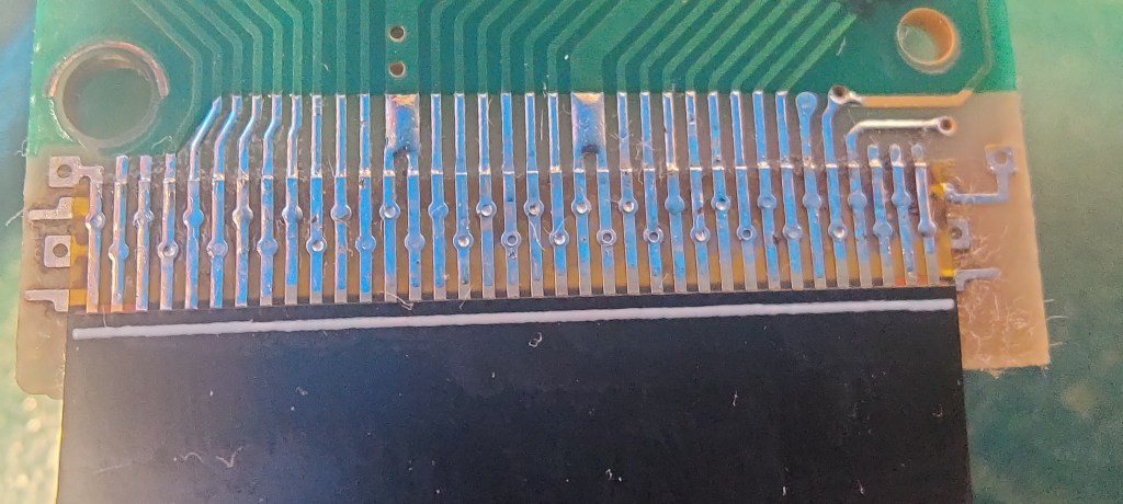
I’ll sweep the soldering iron over all the traces until I feel everything is properly connected. Once that’s done, it’s rinse and repeat for the other side. I always replace both sides because even if one is working, it’s just going to fail soon anyway.
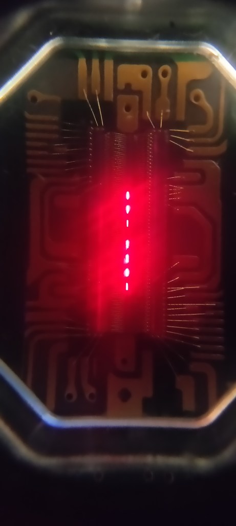
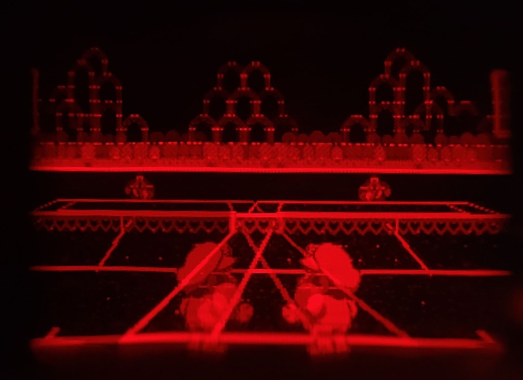
With the display PCBs back in the system, I can now show you how these little guys work. As you can see in the images above, a thin line of red LEDs runs in a strip down the center.
What you see here is essentially a single frame of video. It’s kind of like taking a slice out of the display and viewing the image on its side—like looking at the thin edge of a piece of paper.

There is a lot more to this magic trick, and if you found any of this interesting, you should check out the video “The Fastest Game Console Ever Made?” by The Slow Mo Guys. You won’t regret it.
But until next time, may your hot-bar-applied ribbon cables stay adhered. Later, nerds!
P.S. If you have one of these brilliantly red beauties laying around with this exact issue, send me an email. My day job is fixing this stuff, and I ain’t bashful—I’ll fix it for you, for a fee, of course.

Leave a comment